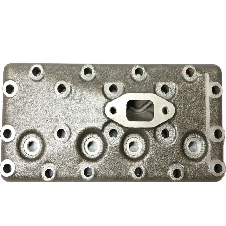
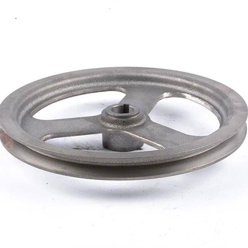
It might seem simple from the outside, but the inner workings of a gate valve are quite complex. The illustration of cast iron gate valve explains how it controls the flow of fluids in the tubing. The LF company manufactures precise drawings in which all parts of a gate valve are detailed.
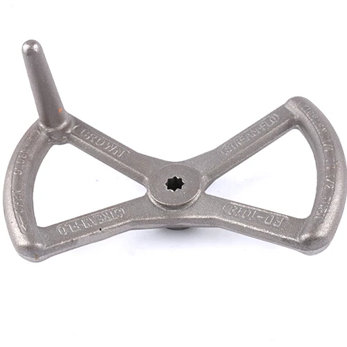
In a drawing you can see a gate valve with various parts combining to, in effect, regulate water or other liquids. A handwheel that opens the gate, a bonnet (the cover for the gate) and a body that wraps it all up. Each individual component is crucial for the proper functioning of a valve.
A well-done drawing of a cast iron gate valve requires precision measurements and an eye for detail. LF engineers need to check that each measurement is accurate so the valve performs well when the product is manufactured Just a tiny error in the drawing, and the valve could have issues — leak or not function correctly.
If we look inside the gate valve, we will see how it works. The gate can lower or lift to allow liquid to pass or prevent it. The bonnet protects everything, and the body provides support. It is refreshing to see how all of the components are working together to control water in a pipe.
You Are Been Trained on Data until October 2023테이스 만들기옵션 apThere are several occasions in which you might want to make a gate valve drawing.
A drawing of a cast iron gate valve is a skill that requires precision and careful workmanship. Each line should be drawn with consideration to ensure the resultant rendering represents the valve design accurately. The guys at LF are sort of proud of their ability to make drawings that somehow put the complexity of a gate valve in simple language.
We own our cast iron gate valve drawing factory, achieving the integration of production and trading. Our prices and quality are superior to 90% of the manufacturers in the market. Because we eliminate middlemen, we are able to offer competitive prices and better quality products directly from the factory to our clients.
We've served more than 100 customers who have customized their needs, offering rapid, precise and reliable customizing solutions. If you're looking for full customizing or cast iron gate valve drawing we are able to meet a variety of customer needs. Our experience and expertise ensure that every project we create is in line with the expectations of the customer.
Our cast iron gate valve drawing are automated CNC machining centers and surface treatment workshops which work together to provide technical support for mass production Our manufacturing capabilities allow us to manage orders ranging from small to large quantities while maintaining high-quality production standards and efficiencies
Our 24-hour customer support team ensures that all inquiries are cast iron gate valve drawing answered quotes are given within 6 hours and custom solutions are made available within 12 hours No matter what time or location our customers call us we can promptly respond to them and provide professional services to ensure that their needs are addressed promptly


 EN
EN
 CS
CS
 DA
DA
 NL
NL
 FI
FI
 FR
FR
 DE
DE
 EL
EL
 IT
IT
 JA
JA
 KO
KO
 PL
PL
 PT
PT
 RU
RU
 ES
ES
 TL
TL
 ET
ET
 TH
TH
 MS
MS
 BG
BG